
If you haven’t read PID Demonstration RIG part 1: Software I highly advise you to do so before continuing, otherwise it might be a bit hard to follow along.
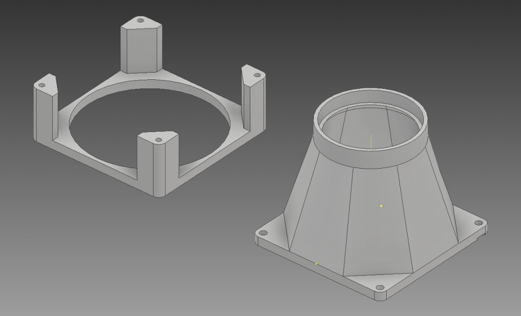
When building stuff like this it is really awesome to have a 3D printer If you can come up with an idea and model it in a CAD software you can hold the physical object in your hand within a couple of hours. So that is what I started with, I designed a foot that will hold the fan and funnel the air into the tube. If I lost you with that sentence, go read part 1.
The parts
I originally designed a some legs to hold the entire contraption as well but as it turns out, computer case fans consume a lot more air than I had anticipated. This meant that despite it being a good 30mm above the mounting board it actually restricted the airflow so much it wouldn’t lift the ping-pong ball. I ended up cutting some legs from a broken plastic container instead, it does look a bit wonky but it works. These are the only pieces I had to fabricate, the only other part that is included in the unit is an acrylic tube that I bought on eBay.
Electronics for the PID controller
The control circuit is not overly advanced, I even made it more complicated than it needs to be for a simple PID regulator. For a PID regulator the only components that are strictly necessary is the sensor for the process value and the mosfet for the control signal, if you have that you can just hard code the gains (Kp, Ki, and Kd) and set-point into the program.

I wanted it a bit more flexible and not be required to re-download the program to the arduino every time I wanted to change the parameters so I added an LCD screen, encoder, and a switch to be able to change the values via a simple HMI.
The finished PID rig
You might notice that there are 2 fans connected in parallel and not 1 as I stated in the first part of this article. I discovered that while 1 fan could lift a ping pong ball it had to run at full speed to be able to do so, and that would have left almost no room for the regulator to work in, so I added a second fan to double the airflow. Computer case fans only draw around 0.15A each so the mosfet can handle it easily.

Even when using two fans I only had a corridor from 200 to 220 in the PWM signal to move the ping pong ball from 10cm to the maximum of 55cm. This serves to demonstrate one of the limitations of the arduino, that it only has 256 discreet steps for PWM generation. Usually this is enough but for precise control over a narrow band it is not ideal.
Figuring out the PID gains
As I mentioned in a previous article this can be the most frustrating step of the entire process, that is why PID functions used by PLC:s and simulation software usually have a calibration function. These functions usually increase and decrease the setpoint according to some schedule and record the response time, overshoot and lag of the system. Based on these values the controller then recommends appropriate values for Kp, Ki, and Kd based on if you want a fast or slow controller. We have no such luck here so instead I figured out the gains manually.
The way I do it is simple and make sure to remember that I said “simple” not “easy” if you are going to try this yourself. First I set a static scaling in the program, if you take a look at the program in the first part of the article you can see the that I multiply the proportional and integral parts with 0.1 and 0.00001 respectively. The derivative part is so small that I can leave that as is. These scalings ensure that I have fine enough control over each part of the regulator when setting the gains from the LCD.
The Proportional gain
When that is done I input a set point and start increasing Kp until I see a response from the system. Here it was really simple, I increased the proportional gain until the ping pong ball was levitating a bit below below the setpoint and left it there for now.
The Integral gain
It is when you add the integral part to the regulator that the frustrating part begins. The main rule here is to start slow and wait for a system response. If you have programmed the regulator correctly you should start to see the system trying to reach the setpoint because now the regulator will strive to minimize the steady state error that is present in the P part of the regulator. If it seems to be moving to slow or not at all you can try to increase Ki a bit more but you really need to wait for the system to settle.
The goal here is more or less to get the system to settle in a stable oscillation around the setpoint, these oscillations are inherent in a PI regulator and the their size is determined by how mechanically unstable the system is. If the system isn’t moving towards the setpoint you should increase Ki and if it is oscillating to much you should decrease Ki. If Ki is to high the system might aven try to over compensate and as a result crash completely.
The Derivative gain
When the system is in a stable oscillation you should add the smallest amount to Kd that you can and wait, if nothing happens increase it and wait a bit more. The oscillations should become smaller and smaller and it should overshoot less and less for every compensation. If you have to high D part the regulator can appear jerky and irregular.
Optimising the regulator
If you think the system behaves as you want you can leave it like that but you might benefit from going back to the proportional part, change it and see how it effects the system as whole. Quite often I find that I can lower the Kp value a bit at this point if it is a PI regulator and raise it if it is a full PID regulator. Just keep in mind that these are my experiences and not rules set in stone.
Regardless you should always let the system stabilize before doing additional changes. How long it takes to settle will depend on the internal resistance in the system itself. Generally you can say that the more mass a system has the more it will resist change and as a consequence you can use a much more aggressive regulator with a higher proportional gain.
PID libraries
I want to say a couple of quick words about Arduino libraries here. I know there are several PID libraries out there with varying degrees of functionality and I admit that some are really nice with built in relay tests etc etc. But one thing that you miss out on when using a library is the full and complete understanding of how a function operates and how parameter changes will effect the system as a whole. And really, when all it takes is approximately 20 lines of code I don’t think there is any reason not to program the entire regulator from scratch and in the process you will learn exactly how a software implemented regulator works.
If you haven’t read it yet, check out my Software based PID regulator article for a longer explanation of what a regulator is.
See you later.