
Introduction
What is a PID regulator? The short answer is that it is an automated control function. The long answer could fill a couple of textbooks. Because of this I won’t delve to deep into the subject but I have an upcoming project that utilises a PI regulator so writing some form of introduction seemed like a good idea for the sake of context. There are a host of longer more exhaustive articles a short Google search away but here is my interpretation of the subject.
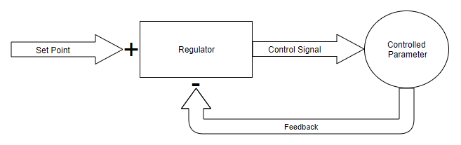
Below is a basic block diagram of a control loop:
The function of the regulator above would look like this:
(Set point-Feedback)*PID=Control Signal
The set point is what we want the feedback to be. The controlled parameter might be any analogue value, such as: speed, heat, height, light, flow etc. The feedback, or process variable (usually called PV), is a measured value of the actual parameter, it is there to tell the regulator how close the system is to the set point, the value we want the controlled parameter to have. And if you take the set point minus the feedback you get the Error. The Error is the difference between the set point and the actual value, this basically tells the regulator how close the system it is to the target value.
Regulator Implementation
In the way I’m going to use it the regulator will be implemented in C code. It can be implemented in several other ways which I won’t mention now. But for my intents and purposes I will only describe how a software based regulator works.
The set point is in this case is a value from a variable in the code. We feed this variable into the regulator, which is only a fancy way of saying a bit of basic maths. I’m not even kidding, a software based regulator is only a bit of basic maths. The regulator sets the control signal. The feedback signal from the controlled parameter is then used to change the variables in the basic maths. This of course changes the control signal, and now we have a control loop.
P Variable
P stands for proportional. As in that the control signal will be proportional to the setpoint. In code it is simply programmed and can look something like this:
Example
Error=(Setpoint-Feedback)
Error*Kp=Control signal
The P variable is called Kp and can be as high or low as you want. There are regulators out there that only use the proportional part, and it can be useful for really slow systems, but they have several downsides. If you think about the equation above, you will realise that the control signal will never actually reach the set point, you will end up with a steady state error. And it doesn’t matter if the P gain is more than 1 or less, the regulator will strive to stabilise at a proportional value to the set point.
The P part is generally used to speed up a regulator, the higher the P variable the faster and more aggressive the regulator. Having a high P variable also leads to a more unstable regulator, with more overshoot and it is quite common that they never settle entirely, P regulators can settle into an oscillating state instead of stabilising completely.
I Variable
I stands for integrated. This part of the regulator takes all the previous control errors into account to determine the control signal. In an embedded system the integral is a variable that is used to store the value between each program loop. We add the value of the current error to the integral that was stored from the previous execution of the program. If the error is negative the integral decreases and if it is positive it increases. Ki s the name of the I variable and it is usually quite a bit smaller than Kp, which means that it is not as great a part of the regulator as a whole.
Example
Error=(Setpoint-Feedback)
Integral = Integral+Error
Integral*Ki=Control Signal
The I part of a regulator is used to overcome the steady state error of the P part and to make sure that the feedback over time reaches the same value as the set point. Remember how I said that the P part can be used alone? Not so with the I part however, please correct me if I am wrong but I have never heard of a stand alone I regulator. The I part is always used together with the P and/or D part for a PI or PID regulator. PI regulators are used frequently for stable systems were you don’t mind a bit if overshoot for instance.
Regulator Windup
One thing too keep in mind when it comes to the integrating part of a regulator is that as soon as the system is turned on, the integral starts to grow. This happens because there is almost always some noise from the feedback measurement, the signal isn’t completely zero even if the system is at rest. Over time, when the integral grows large enough, the regulator tries to correct the error and the system moves, or turns on, or whatever depending on what type of system you’re controlling. This is called Integral Windup. A good way to combat this is to have a reset function in your code, i’m still talking about software based regulators here by the way, you can code it so that when set point is less than X, Integral=0.
D variable
D stands for Derivative. In the same way that the I part is a value remembering how far the system moved from being at rest, the D part tells the regulator how close the system is to reaching the set point. To be able to do this we need to keep track of the Error over time, we save the error value from one program iteration to the next, like in the example below.
Example
Last Error=Error
Error=(Set point-Feedback)
Derivative= Error-Last Error
Derivative*Kd=Control Signal
The D part is rarely used alone and its main function is to dampen a large P part of a regulator. The idea here is that the further away from the set point the system is the quicker we want the system to move. This means that it needs a large P part, but a large P part also leads to a lot of overshoot and an unstable system, which we don’t want. The D part of a regulator is positive before the half-way mark to the set point but after that it becomes negative and when any part of a regulator is negative it decreases the control signal. That’s how the D part prevents overshoot and and dampens an aggressive P part.
A stable system might not need a D part at all, the system itself helps to dampen overshoot and oscillations. But an unstable system, such as a Quad-copter for example, needs a D part to even function.
The Equation of a PID regulator
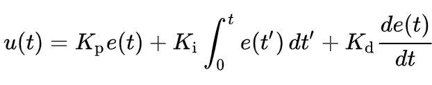
I couldn’t have a post about PID regulators without showing the full equation for a PID regulator, this is one of the most common ones. It is in what is called Additive Parrallell Form. You can also use it in Multplicative form, in series, or in parallell. All these different forms, or equations, is only describing how the parts of the regulator should relate and effect one and other.
I wanted to show the equation but I didn’t want it to be the first thing you saw because it looks really complicated and I didn’t want to loose you directly. If you have read the article you should be able to understand the equation. Kp, Ki, and Kd you’re already familiar with the rest is just as easy.
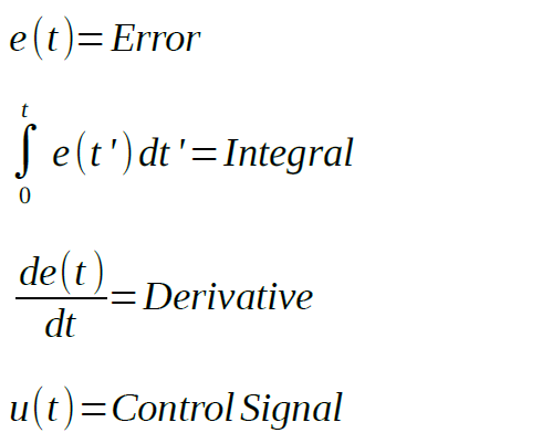
The equation is only the mathematical way of describing what I wrote earlier in the article.
The size of the parts or Regulator Tuning
There are several different ways of determining the optimal values, or at least starting values for Kp, Ki, and Kd. And the simplest way is trial and error. Remember that I said “Simple” not easy if you want to try this.
Experimental way
Set the PID values to something small, the P part should probably be around 3-5 times as large as the I and D part. The I and D part can be about the same value at the start, but if you have noisy signal you can lower the I part to combat Windup. Start the system and make sure you have some way to log the Control signal and Feedback. If you are using a software based regulator in an embedded system, such as an Arduino, the easiest way is probably writing the values into a spread sheet stored on an SD card.
After testing the system open the file in a spreadsheet program and use the graph function to draw the trend line of the feedback signal. When you have the visual representation of the system it is a lot easier to decide how to adjust the PID values. But be warned, it can take a lot of experimentation and frustration the first couple of times you do this. The best advise I can give you is to only change one variable at a time, and constantly checking how the regulator responds after each change. This will take a lot of time but is probably the easiest way of doing it. Otherwise you can not be sure of how each change effected the regulator.
Ziegler Nichols
Ziegler Nichols is a slightly more scientific way of setting the PID variables. It is greatly simplified by having the ability to view the graph live as the system is running, but it can be done the same way as I already described, by logging the values into a spread sheet.
You set Ki and Kd to zero, then you increase the Kp value until the system is in a stable oscillation. This ultimate Kp gain is called Ku, and the time period of the oscillations are called Tu. Measure the time it takes for the Feedback, or process variable, to complete half a period in your graph. This is your Tu value. Then you set your Kp, Ki, and Kd values based on the Tu value.
| Control Type | Kp | Ki | Kd |
| P | 0.5Ku | – | – |
| PI | 0.45Ku | 0.54Ku/Tu | – |
| PD | 0.8Ku | – | KuTu/10 |
| PID | 0.6Ku | 1.2Ku/Tu | 3KuTu/40 |
| Some Overshoot | Ku/3 | 0.666Ku/Tu | KuTu/9 |
| No Overshoot | Ku/5 | (2/5)Ku/Tu | KuTu/15 |
Table 1: Values for Ziegler Nichols Tuning, courtesy of Wikipedia.
For hobby applications, and simple industrial process control, one of these two methods should be enough to get a decently performing regulator. If you are dealing with something more critical you are probably better of picking up a text book than reading a blog post anyway.
You might encounter the terms Ti and Td when reading about PID regulators. These are the Ki and Kd values, or Gain, considered in the time domain. They are related to Ki and Kd like this:
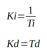
In more advanced control theory there is a function called Laplace transform used to calculate the regulator parameters in the frequency domain instead, but to do this you need to transform the values from time to frequency, but that is way beyond this article and that is all i’m going to say about that.
Conclusion
Like I said, only some simple maths. All the examples above are how a software based regulator would be programmed, or how the logic in the program would work. It is not in any particular language because there are very many out there that I felt it easier to explain the logic first and how to implement it in C code in an upcoming post please stay tuned for that.
I hope I haven’t lost you along the way because this post ended up way longer than I had planned, I guess I had a lot to say about the subject. If you have any questions or comments feel free to post them in the comment section or send me an email at: offhoursengineering@gmail.com